Manual gearbox
Transmission, removing
Note! As the illustrations in this service information are used for different model years and / or models, some variation may occur. However, the essential information is always correct.
Disconnecting the battery leadRemove the battery lead. See Note when disconnecting/connecting the battery lead . |
Removing engine compartment components | |
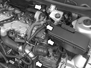
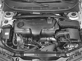 | Remove:-the engine cover -the upper engine stabilizer brace Brake fluid reservoir, replacing -the air filter housing complete with fresh air hose. Unhook the turbo control valve and connector from the air filter housing. Pull up the air filter housing from its mounts. |
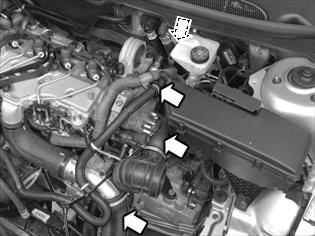 | Remove:-the charge-air pipe for the turbo, leave the hose on the turbo in place -the hose between the inlet manifold and charge-air cooler from the inlet manifold -the clamp for the cable harness on the engine -the nut for the rear engine pad as well as the vacuum hose. Leave the nut in place on the engine pad by a few threads. Fold the hose aside. |
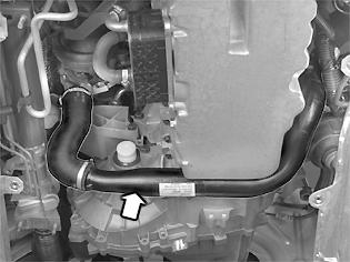
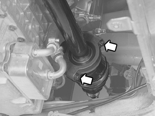
Removing coolant hose from passenger compartment heater | |
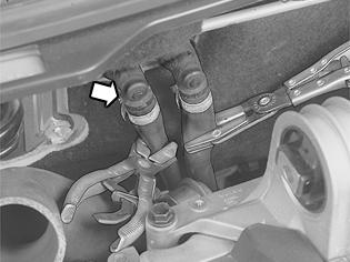 | Clamp the hoses with hose clips. Turn the quick-coupling a little in the arrow's direction, so that the lock opens. At the same time, pull the inner coolant hose from the coolant pipe, straight out. |
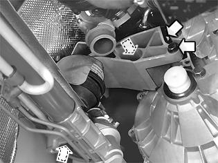
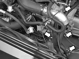 | Block the hose between the brake fluid reservoir and the clutch cylinder with hose pliers. Remove the lock from the quick-coupling on the junction at the clutch cover and remove the hose. Collect the brake fluid that runs out, protect the openings from contamination. Remove:-the ground cable from the transmission and the sub-frame -the screw for the clamp for the servo cable on the sub-frame -the clamp and the hose from the lower charge-air pipe. |
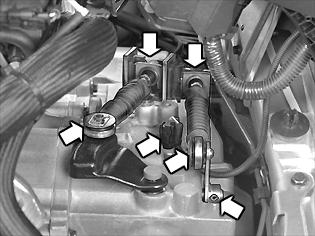 | Use jimmy bar 999 7077 to detach the ball joint for the gearbox cable from the lever. Detach the casing for the gearbox cables from the bracket in the gearbox by pressing the locking sleeve backwards. Lift up the gearbox cables. Remove:-the lock pin from the lever -the lever from the transmission -the connector for the back-up (reversing) light switch. |
Installing the lifting beam and lifting hook on the engine lifting eyelet | |
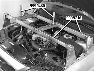 | Position lifting beam 999 5716 on the wheel arch and directly above the engine's lifting eyes on the left and right side. Use lifting hook 999 5460 on the engine's right side with a clearance of approx. 10 mm. Tighten to light contact on the left side. Lift up the car. |
Removing the air baffle and splash guard under the engine | |
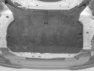
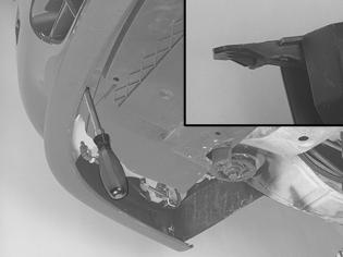 | Remove:-both the front wheels -the splash guard under the engine -the screws for the air baffle. Press in the catches holding the air baffle and remove it. |
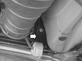
Removing screw for the cable conduit | |
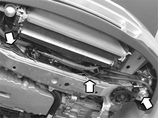 | Unhook the cable duct from the sub-frame. Remove the 2 screws for the heater, unhook the heater from the mounting and leave the heater hanging freely in its upper mounting. Detach the heater's fuel line from its holders on the sub-frame. |
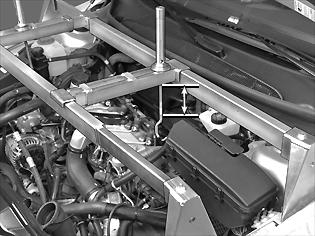
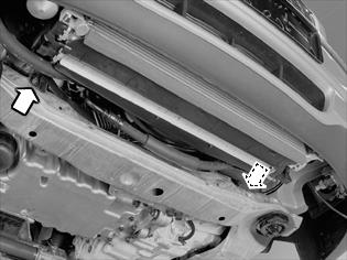
Removing cross members from body | |
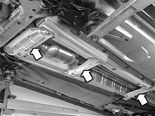 | Remove:-the screws for the front cross member -the brake pipe from the holders -three screws. Slacken off the fourth screw on the two rear members. Then turn the members to the side so that the exhaust pipe is exposed. |
Remove the collision protection system over the steering gearNote! Right-hand drive cars only. | |
 | Remove:-both screws -the collision protection system. |
Removing screws and nuts for the engine pads and torque rod | |
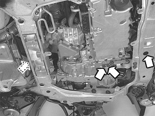 | Remove:-the screw for the front engine pad - sub-frame -the screws for the torque rod. |
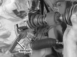
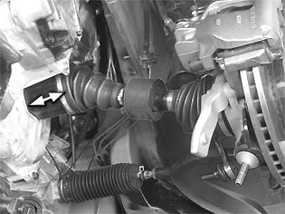
Measuring the position of the tie rod in the steering gear | |
 | On one side, measure the length of the track rod in relation to the steering gear housing. Note the measurement. |
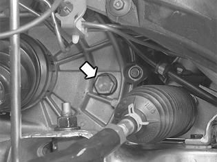
Exposing the steering shaft joint | |
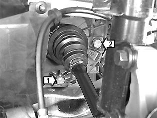
 | Remove the screw, 1, to the joint between the steering gear and the steering wheel shaft. Press the joint up from the steering shaft. |
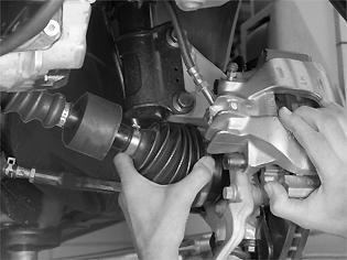
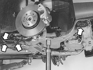
Disconnecting the front suspension components | |
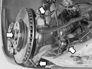 | Disconnect the ABS cable from the mounting in the strut. Remove:-the screw for the drive shaft using a screwdriver in the brake disc vents -the link from the anti-roll bar (left side) -the nut for the tie rod (left side) -the nut for the ball joint-link arm. Clean the exposed threads outside the nut and spray with rust solvent before removing the nut. Note! Counterhold at the ball joint pinion using a Torx TX 40 when removing the nut. This is so that the ball joint boot does not turn. |
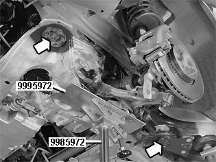
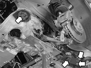
Removing the screws from the sub-frame support plates (both sides) | |
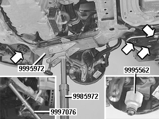 | Remove the screws from the sub-frame support plates (both sides). Apply the mobile jack 998 5972 together with fixture 999 5972 lightly under the sub-frame's right side. Slacken off the screws for the sub-frame on the right hand side and check that the nuts are still secured by at least 5 revolutions. Remove the jack. Unhook the control arm from the ball joint. Install protective sleeve 999 5562 . Hold the sleeve in place with the nut for the ball joint. Fold out the strut and remove the drive shaft from the wheel hub, be careful so that the rubber gaiter is not damaged. Hold the strut aside using a tensioning strap for more space when removing the drive shaft. |
Removing the cap for the drive shaft support bearingRemove:-the drive shaft's support bearing cap according to Removing the transmission -the drive shaft by pulling it straight out from the transmission. Install seal plug 999 5488 for the transmission. |
Lowering the sub-frame | |
 | Position the mobile jack lightly applied under the left side of the sub-frame. Remove the sub-frame screws. Note! When lowering ensure that the screws for the steering gear release from the sub-frame. Ensure that the ball joint pinion releases from the control arm. Remove the mobile jack and let the frame hang loose. |
Removing drive shaft from wheel hub | |
 | Fold out the strut and loosen the drive shaft from the wheel hub. Hold aside the strut with a tensioning strap for more space when removing the transmission. |
Removing lower charge-air pipe between charge-air cooler and turbo | |
 | Remove:-the hose from the turbo -the charge-air pipe from its mounts on the engine. |
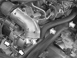
Removing the rear engine mounting | |
 | Remove:-the screw for steering gear-engine pad, move the steering gear backwards towards the firewall -the engine pad and engine mount from the engine |
Lowering engine and transmission | |
 | Lower the engine and gearbox on the left-hand side using the hook. Check that no hoses or cables are being stretched or trapped when the engine is lowered. Lower the engine so that 100 mm of the lifting hook's free threads can be seen. Raise the car. |
 | Carefully pull out the coolant hose past the connection on the EGR cooler. Remove:-the screws for the starter motor - transmission (2 pcs.) -the screws for the transmission - engine (4 pcs.) |
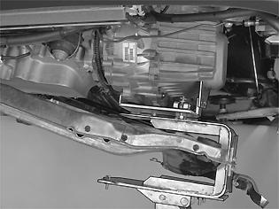
Installing fixture on mobile jack and transmission | |
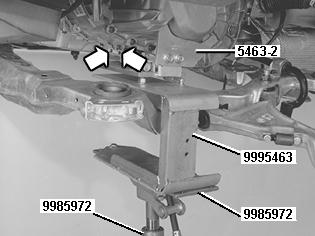 | Raise the car. Install the fixture 999 5463 for fixture 999 5972 . Use both fixtures together with mobile jack 998 5972 . Fit the support plate (part number 5463-2) and the transmission, see figure. Tighten the fixture with the two torque rod screws. Apply the mobile jack lightly against the gearbox. |
Removing all screws for transmission-engine | |
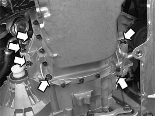 | Remove the remaining 6 screws for the transmission-engine. |
Removing the gearbox | |
 | Make sure that the transmission is removed straight out in relation to the engine, so that no stresses are created in the disc's center. Note! Lower the gearbox slightly when it is being removed so that it will pass the side member freely. Remove the gearbox. |
Transmission, installing
Note! As the illustrations in this service information are used for different model years and / or models, some variation may occur. However, the essential information is always correct.
Note! For tightening torques, see: Tightening torque .
Cleaning and lubricating the input shaftThe input shaft must be lubricated before a manual transmission is installed. See Cleaning and lubricating the input shaft for manual transmissions . |
Checking before installing | |
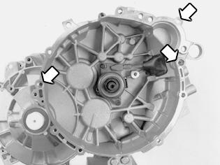 | Check that the transmission and engine mating surfaces are absolutely clean. Check that the guide sleeves towards the engine are in position and are free of faults. Lubricate the holes in the transmission (for the guide pins and the starter motor). Use a little grease. |
Adjusting the position of the transmission and engine | |
| Adjust height and angle with the mobile jack and the transmission fixture. Locate the transmission on the engine. Ensure that the transmission goes straight in, in relation to the engine, and that no deviation occurs in the clutch driven plate center. Guide the transmission cover onto the guide sleeves on the engine and the starter motor. |
Installing and tightening the screws for the transmission | |
| Install the 6 screws for the transmission - engine. Tighten the screws alternately and crosswise to light contact. At the same time, check that the whole of the transmission is in contact with the engine. Following which, tighten the screws crosswise. Remove the fixture from the transmission. Lower the car. |
Installing the remaining screws on the transmission and starter motor | |
| Install:-the screws for the transmission-engine (4 pcs.). Tighten. -the screws for the starter motor. Tighten. Position the coolant hose inside the hose for the EGR cooler. |
Lifting the engine - transmission | |
| Lift the engine and transmission to slightly above horizontal for better access when installing the engine pad on the engine mounting. Raise the car. |
Installing the rear engine mounting | |
| Install:-the rear engine mounting and the engine pad together with the heat deflector plate. Hold the engine pad limiter (cable) in place during installation. Use a tie strap -the screws for the engine mount (3 pcs.). Tighten. -a new nut loosely on the engine pad -the screw for the steering gear - engine pad loosely. Check and if necessary align the bearing for the steering shaft in the boot when installing the steering gear. See Installing the gearbox . |
Installing the lower charge air pipe | |
| Install the charge air pipe and the hose on the turbocharger (TC) and engine. |
Installing the left drive shaft on the transmission and the wheel spindle | |
 | Note! Ensure that the seal is in place on the drive shaft. Install the sealing ring for the constant velocity joint housing. See Seal CV joint housing, replacing . Press in the constant velocity joint housing firmly so that the snap ring engages in its groove in the transmission. Pull the constant velocity joint to check that the drive shaft is secure. Locate the drive shaft in the wheel hub. Install a new screw loosely in the drive shaft. |
Installing the sub-frame on the bodywork | |
 | Note! Use new screws. Lubricate the screw threads. Lift up the sub-frame until it is about 150 mm from the side member. Secure the power steering pipe at the front edge of the upper side of the sub-frame using the rubber covered clamp. Install the screw. Finger tighten. Note! When the sub-frame is raised, ensure that the screws for the steering gear locate in the frame. Ensure that the ball joint pinion for the spring strut is aligned in the control arm. Install:-the new screw and the support bracket at the rear -the screws loosely in the bracket -the bracket for the additional / parking heater at the front. Use a new screw. Tighten the sub-frame screws. Tighten to light contact. Remove the mobile jack. |
Installing the right drive shaft on the transmission, wheel spindle and control arm | |
 | Install the cap for the drive shaft's support bearing. Tighten Note! Ensure that the seal is in place on the drive shaft. Install the sealing ring for the constant velocity joint housing. See Seal CV joint housing, replacing . Locate the drive shaft in the wheel hub. Install a new screw loosely in the drive shaft. Press down the control arm. Locate the spring strut in the ball joint pinion for the spring strut in the control arm. Position the mobile jack lightly applied under the right side of the sub-frame. Remove both the sub-frame screws. Install:-new screws in the sub-frame Note! Lubricate the screw threads -the screws loosely in the rear edge of the support plate. Tighten the sub-frame screws. Tighten to light contact. Remove the mobile jack. |
Tightening the screws for the sub-frame on both sides | |
 | First tighten the frame's screws, see Tightening torque . Use angle gauge 951 2050 . Then tighten the screws for the frame's brackets. |
Installing the front/rear screw for the engine pad and the mounting for the torque rod in the sub-frame | |
| Install:-the screws for the front engine pad. Tighten front/rear and the rear screw. -the torque rod's bracket to the transmission. Tighten in accordance with Tightening torque . Note! Use new screws. |
Installing the collision protection system over the steering gear | |
| Applies only to right-hand drive carsInstall both screws. Tighten. |
Installing the steering wheel shaft joint | |
| Fit the steering shaft universal joint on the steering gear. Install a new steering shaft screw. Tighten according to: Tightening torque . Connect the cable to the step motor/solenoid. Check the tie rod's position according to: Transmission, removing . |
Check the transmission oil level | |
 | Top up if necessary. P/N: 116 1423-7. Volume: 2.1 liters. Tighten the plug. |
Installing and tightening front suspension components | |
| Install the nut for the ball joint pinion. Counterhold the ball joint pinion while tightening so that the ball joint boot cannot turn. Use a new nut. Tighten. See: Tightening torque . Tighten the screw for the drive shaft. Use new screw. Counterhold with a pry bar in the brake disc. Tighten according to Tightening torque . Use angle gauge 951 2050 . Install:-the link for the anti-roll bar. Counterhold the ball joint pinion while tightening so that the ball joint boot cannot turn. Use a new lock nut. Tighten. -the nut for steering joint according to: Tightening torque -the ABS line in the mounting in the spring strut -the fender liner with the support plate and nuts and the soundproofing over the drive shaft. |
Installing the cable duct | |
 | Install:-the cable duct on the sub-frame -the additional heater / parking heater on the mounting in the sub-frame -the fuel line in the holders in the sub-frame -the front splash guard -the splash guard under the engine -the wheels. See Installing wheels . |
Removing the lifting beam | |
| Lower the car. Remove the lifting beams and hooks from the engine. |
Installing the lever and transmission cables | |
| Install:-the connector for the back-up (reversing) light switch -the lever with the lock pin in the transmission -the transmission cables in the transmission and levers Note! The yellow marked cable must be outermost. |
Installing the hose nipple on the junction for the clutch bearing | |
| First push the catch in the junction. Then press the hose nipple into place. Ensure that the clip is seated in its groove. Remove the hose clip. Bleed the clutch. Use only Volvo Genuine parts brake fluid DOT 4+. Install:-the ground lead in the transmission and the sub-frame -the clamp and the hose on the lower charge air pipe. Tighten the screw in the clamp on the servo pipe. |
 | Tighten nut for the engine pad. Install:-the vacuum hose on the engine pad -the hose from the charge air cooler to the intake manifold -the charge air pipe on the turbocharger (TC) and engine -the hose on the heater -the screw in the clamp for the cable harness. |
| Install:-the torque rod. See Brake fluid reservoir, replacing -the engine cover -the air cleaner (ACL) housing with all hoses and electrical terminals. Start the engine and bleed the cooling system. Install the battery lead. See Note when disconnecting/connecting the battery lead . Top up and check the engine coolant level. Note! Use Volvo Genuine parts coolant only. |
Seal, primary shaft, replacing
Removal
Note! As the illustrations in this service information are used for different model years and / or models, some variation may occur. However, the essential information is always correct.
Note! Preparations, see Transmission, removing .
Removing the clutch cylinder | |
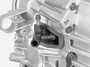
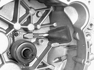 | Remove the rubber seal from the clutch cover. Move it inwards on the pipe towards the clutch cylinder. Pull out the retaining clip locking the quick-release connector on the pipe to the junction. Remove the adapter. Keep it in a plastic bag to prevent contamination. Install a protective plug in the end of the pipe. Remove the clutch cylinder. Clean the mating surfaces in the clutch cover. Check any leakage from the gearbox. |
Installing the extractor for the primary shaft seal | |
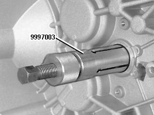 | Tap in the extractor for the primary shaft seal. Use extractor 9997003 . Note! The screw and socket must be unscrewed when tapping on the extractor. Tap the tool into the seal. Tighten the inner socket. Counter hold the outer part at the same time so that the tool expands against the seal. Tighten the screw in the extractor. Remove the seal. |
Installation
Installing the new primary shaft seal | |
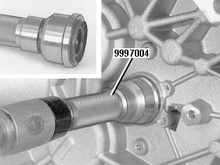 | Lubricate the lip of the primary shaft seal. Use grease, P/N 1161241-3. Use drift 9997004 when installing the primary shaft seal. Pull the sliding drift sleeve forward. Press the seal into place. Guide drift on primary shaft. Tap in the seal until the sliding drift sleeve is against the gearbox and in the rear sleeve position. |
Installing the clutch cylinder | |
| Tighten the screws. Tighten to 10 Nm. Thread the rubber seal onto the pipe with the boot turned towards the clutch cylinder. Remove the protective plug. Install the junction. Always use a new quick-release connector with a rubber seal. Lubricate the rubber seal using a drop of brake fluid. This facilitates joining. Press the pipe into the junction. Lock the pipe using the clip. |
Installing the rubber seal for the pipe in the clutch cover | |
 | Ensure that the rubber seal locates all the way around. Note! Follow-up work: To install the gearbox, see Transmission, installing . |
Gearbox fluid, replacing
Removing splash guards and front wheels | |
 | Raise the vehicle. Remove:-the splash guard under the engine -the left front wheel. Draining the gearbox fluidCollect the oil in a container. Remove the drain plug. Drain the oil. Install the plug with a new gasket. Tighten to 35 Nm. |
Checking the oil level | |
 | Remove the level plug and fill with oil. Use only Volvo gearbox oil P/N 116 1745 (1 litre). Volume in the gearbox 2.1 litres. Install the level plug with a new gasket. Tighten to 35 Nm. |
Installing splash guards and front wheelsInstall:-the splash guard under the engine. Tighten the screws. Tighten to 25 Nm -the wheel. See Installing wheels . |